The intake screen and valve assembly is an economical pump intake control system that integrates the stainless-steel wool screens with a pressure-activated cone valve that can be set to open at a specific differential pressure. A valve can be installed at the end of the screen, or multiple valves can be configured between screen sections to maximize pump protection and extend pump life.
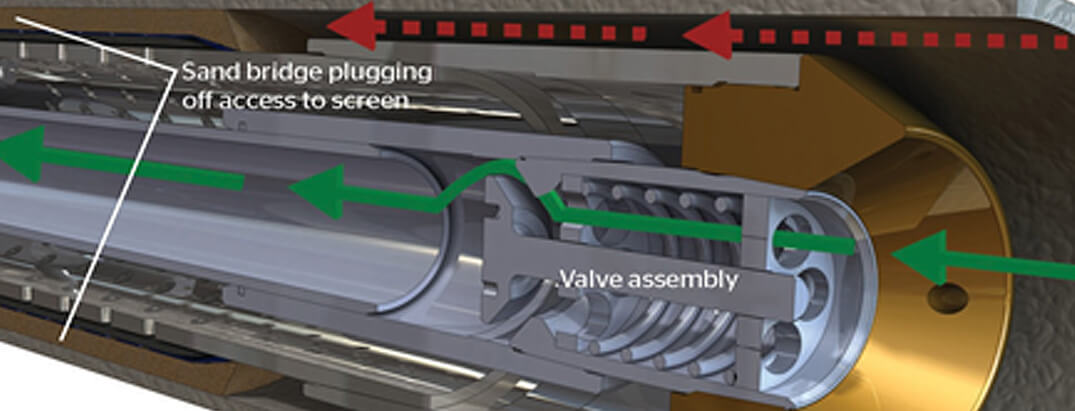
Single valve assembly at the end of sand control screen showing sand bridging, with the valve open and allowing flow through the valve into the tubing. .
INSTALLATION
The activation pressure for the assembly’s cone valve is set prior to installation. The assembly is usually suspended from a packer slightly below the pump itself to facilitate easier removal, or it can be hung from the pump, if desired. The assembly can run in vertical, deviated, and horizontal wellbores.
Startup
On installation, the valves are closed, causing hydrocarbons to flow radially through the screen into the wellbore. The screen’s compressed stainless-steel wool features triangularshaped pores with an initial open flow area of 40% and higher retained permeability than other screens. The pores vary in size from 15 to 600 microns, and their irregular shape resists plugging. As sand is stopped at or near the screen surface, open space surrounds these particles and the retained permeability of the screen itself remains high.
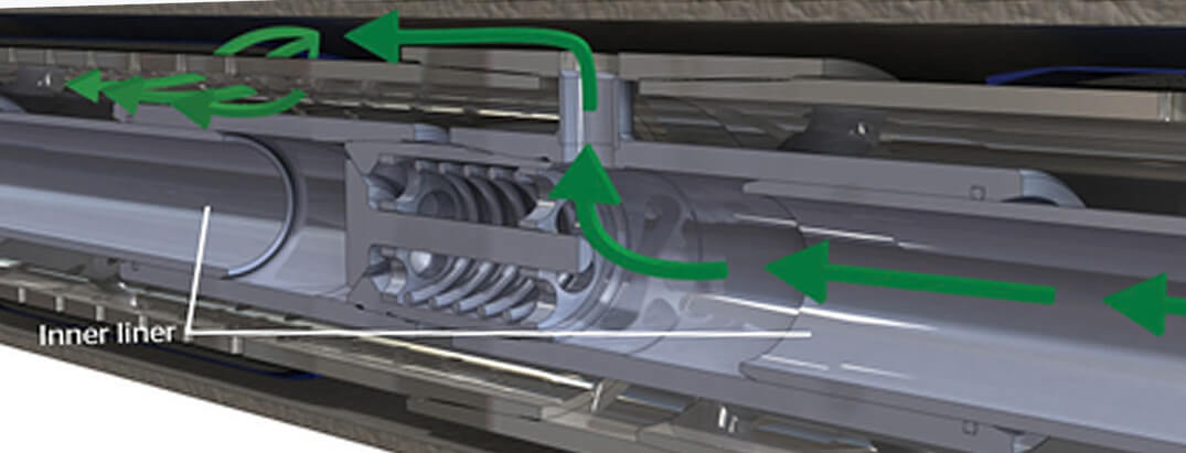
Multivalve assembly installed between screen sections. Sand bridging opens the valve, diverting flow into an inner liner, out a port, and through another screen section with its valve closed, whichextends pump life.
Operation Over Time
Over time, formation particles fill the annular area between the outer surface of the assembly screen and the production casing wall. As the cavity fills with sand and the particles consolidate, pressure drops across the sand pack, which slows and eventually stops fluid flow. When the pressure drop across the sand pack reaches the preset value, the cone valve opens and allows flow directly through the pump intake. Only at this stage will sand begin to cause wear on the pump, extending the life of the pump by the total operating time during which the cone valve remained closed.
Depending on the application, operators may choose to extend the pump life further and delay the need for a workover by installing more than one section of screen with valve assemblies between sections and an inner liner. Sand bridging between the screen and casing causes the valve in that section to open, diverting flow through the cone value and into an inner liner. The fluid passes out a port between the joints of the screen to another screen section with its valve closed. The pump life is extended until sand bridging opens that valve and flow through subsequent valves reaches the pump.
Pump Life
The amount of time the pump life is extended depends on the amount of solids produced and these solids flowing directly into the
pump. These factors will be influenced by the
Intake screen and valve assembly Specifications |
|||||||||
|---|---|---|---|---|---|---|---|---|---|
| Connection | NU or EU Standard | Standard 8 Round LTC | |||||||
| Nominal pipe OD, in [mm] | 2.375 [60.325] | 2.875 [73.025] | 3.500 [88.900] | 4.000 [10.160] | 4.500 [114.300] | 5.000 [127.000] | 5.500 [139.700] | 6.625 [168.275] | 7.000 [177.800] |
| Stainless-steel screen OD, in [mm] | 3.000 [76.200] | 3.500 [88.900] | 4.050 [102.870] |
4.550 [115.57] | 5.050 [128.27] | 5.550 [140.97] | 6.050 [153.67] | 7.130 [181.102] | 7.650 [194.31] |
| Valve section intake OD, in [mm] |
3.000 [76.200] | 3.500 [88.900] | 4.050
[102.870] |
4.550 [115.57] | 5.050 [128.27] | 5.550 [140.97] | 6.050 [153.67] | 7.130 [181.102] | 7.650 [194.31] |
| Valve section length, in [mm] | 6.000 [152.400] |
6.500 [165.100] |
7.000 [177.800] |
7.500 [190.50] | 8.000 [203.20] | 8.500 [215.90] | 9.000 [228.600] | 9.500 [241.300] | 10.000 [254.000] |
| Valve opening pressure, psi [KPa]‡ | 30 – 150 [206.8 – 1034.2] | ||||||||
| Overall length, ft [m]§ |
60–100 [18.29–30.48] based on 15–20 [4.57–6.09] per joint of screen, typically configured using 3–4 joints | ||||||||
‡Opening pressure can be set to lower than 20 psi [137.9 kPa] for special requests.
§3.5-in [88.9-mm] OD Stainless-steel screen weighs 10–11 lbm/ft [16.32–19.59 kg/m].